TeensyMaestro Kit - Links and building instructions
Introduction
Thanks very much for your purchase of the kit. I expect you’re keen to get started so I’ll try and keep this brief!
All the components (including a blank SD Card) are stored within the six component packs. Each pack has a BOM attached to it. Feel free to empty all of the packets into a container for easy retrieval, checking the contents as you go.
PCB build
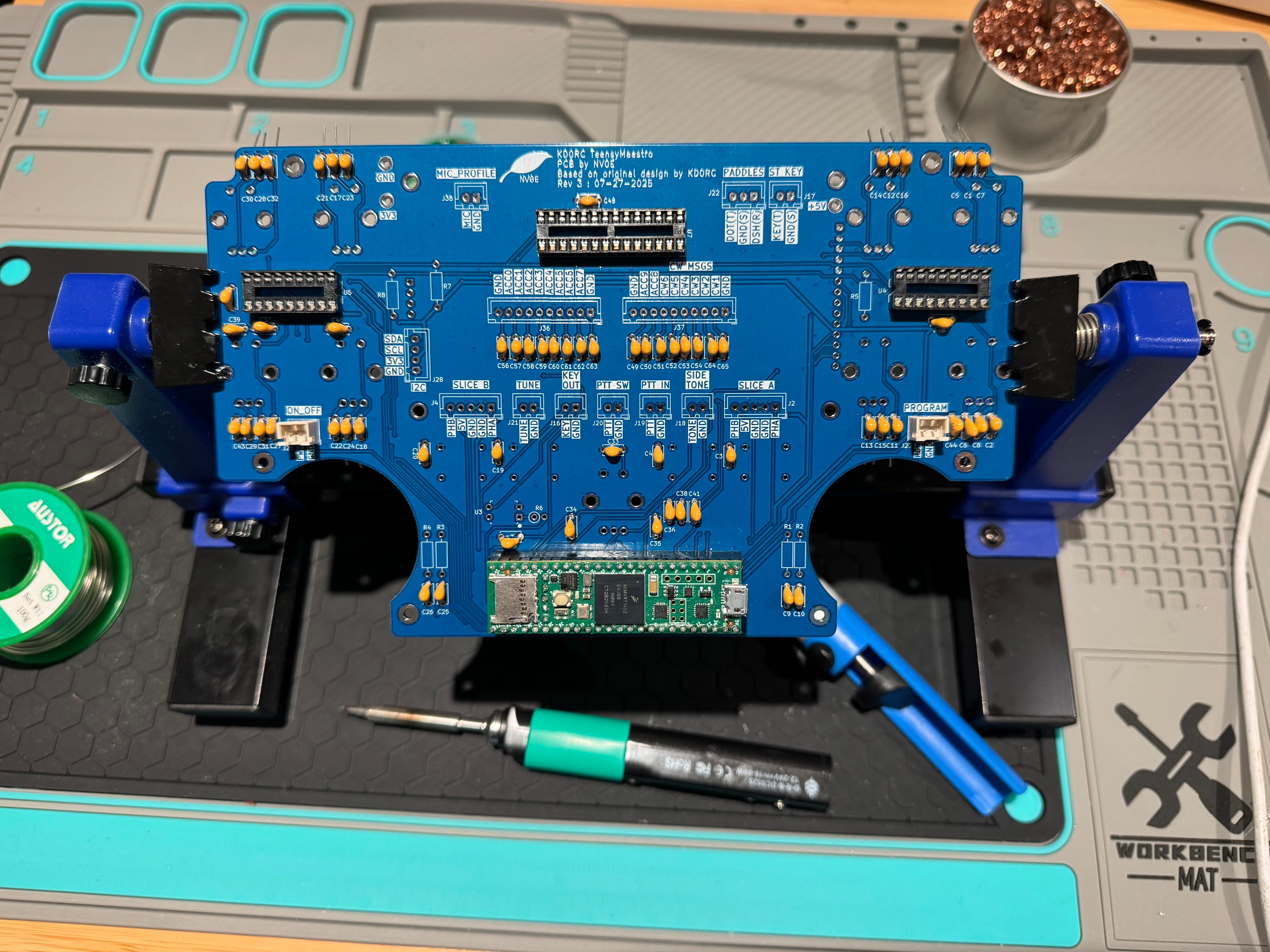
Simon, NV0E has written some great instructions on the construction of the main PCB as well as the modification of the LCD.
Differences
PCB Assembly ‐ (3) Front of PCB; 4. Standoffs [link]
With the case being different in this kit these standoffs are not used.
Update 28th September - Thanks to Jonathan, G4IVV who suggested it is useful to use these standoffs. I’ve started to include them with the kit.
Slice Encoder Connections [link]
The encoders in this kit have different coloured wires. The mapping is as follows.
| Purpose | Encoder Wire | JST-XH Header Connector Wire | Pin Number |
|---|---|---|---|
| Phase B | White | Blue | 1 |
| GND | Shield | Green | 2 |
| GND | Black | Yellow | 3 |
| +5V | Red | Black | 4 |
| Phase A | Green | Red | 5 |
Assembling the case
The case comes in two parts, the main body and the back panel.
Back panel
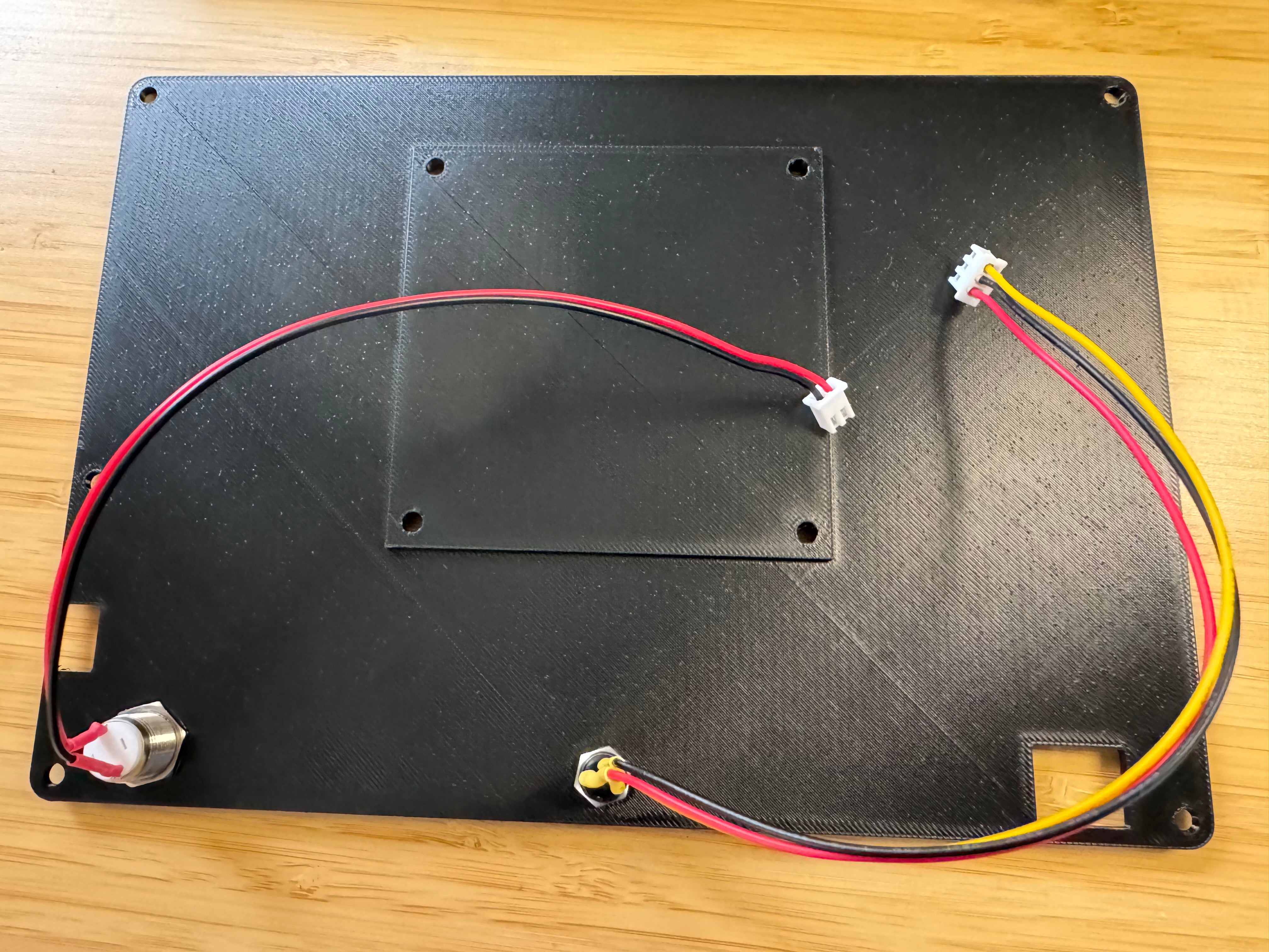
The only components attached to the back panel are the power button and any 3.5mm sockets you have purchased. All others are mounted on the main body with access holes in place in the back panel.
I would recommended you fit the components in the panel early prior to (carefully) soldering the cables. This saves any issues fitting them afterwards.
Main case
Front panel
Ensure there are no print artefacts left in the inset for the front panel. These should come off easily with a non-sharp object.
The printed front panel should fit in place snuggly and the four M4x8mm bolts should be placed in the four outer holes.
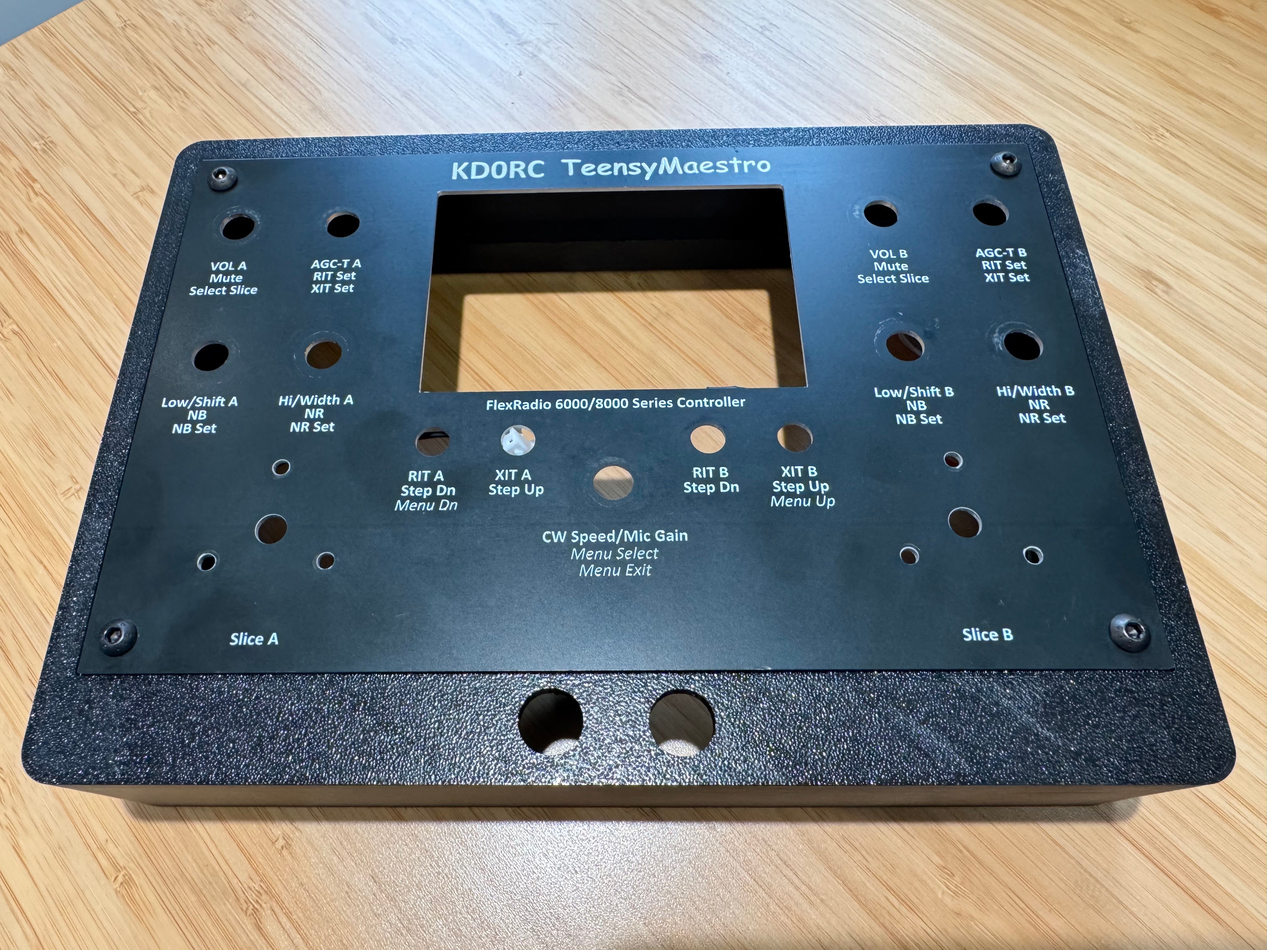
The four M4 nuts should be fitted to the back to securely fix it into place.
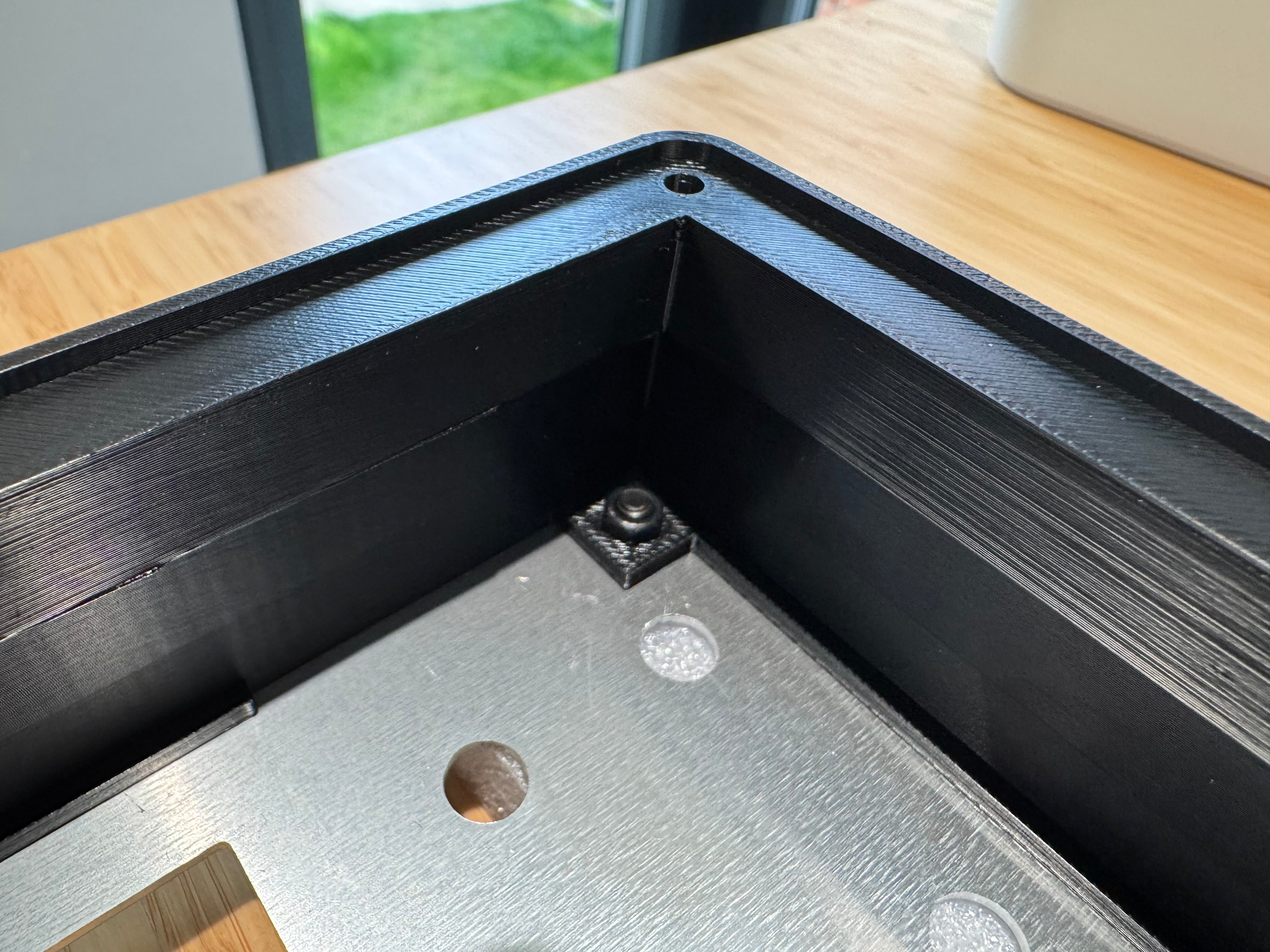
Once you’ve done this place this face down on a soft surface to save from any scratches.
For the purposes of clarity, I removed the front panel for the remaining pictures.
Program button
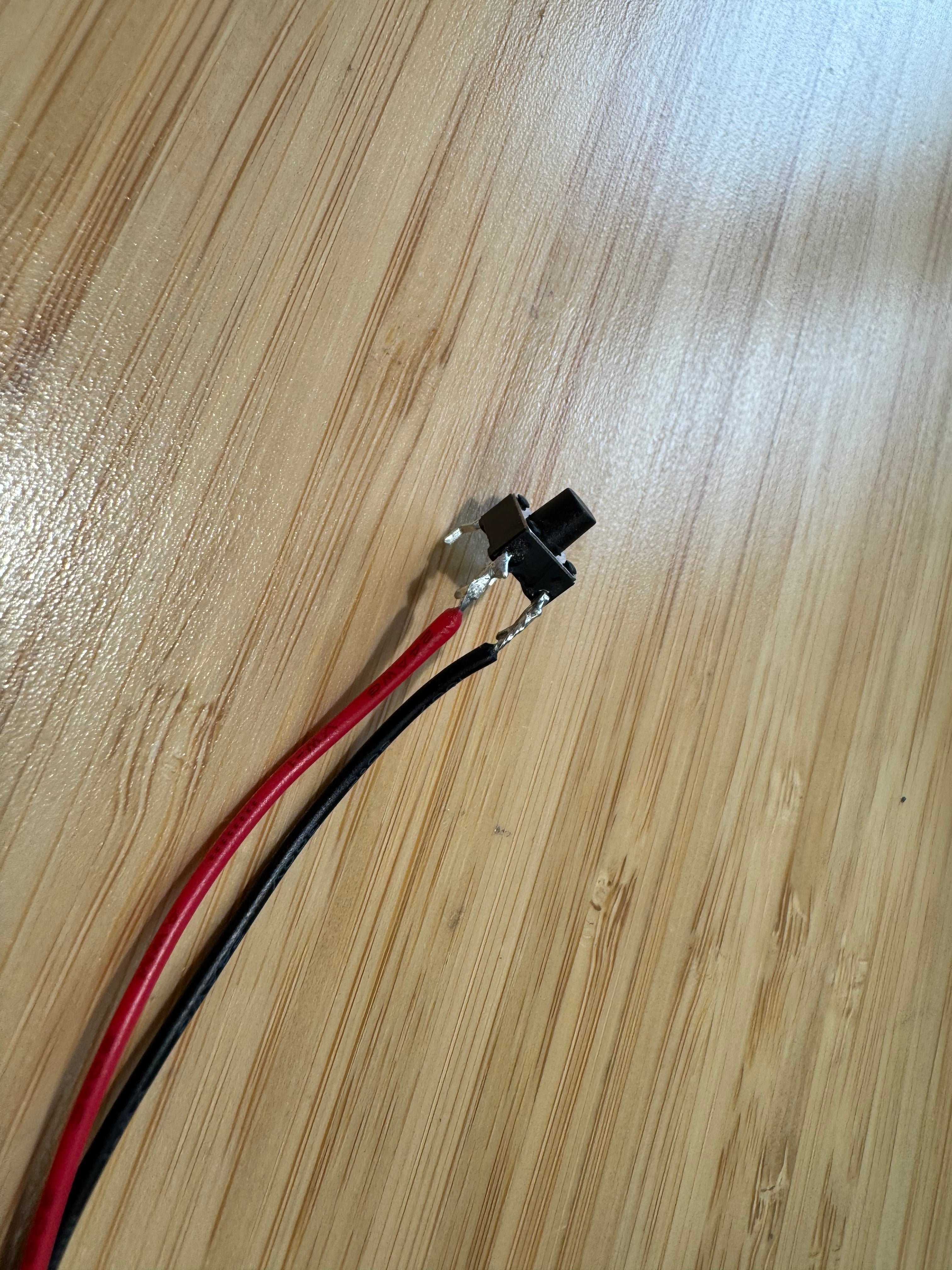
This (Momentary Tactile Push Switch - 6mm) is one of the more fiddly mounts.
The cable should be soldered like this (please note the orientation of the switch and its ’legs’).
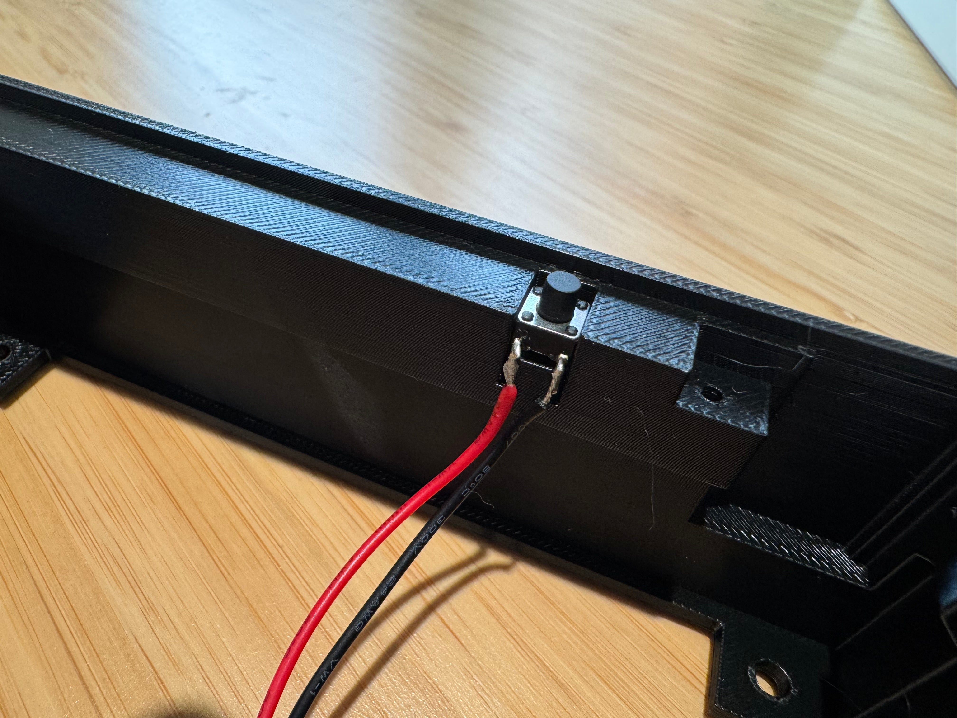
It should then be mounted in the case like so, the unsoldered legs should fit down the side of the case and the switch should sit below the cut in the case.
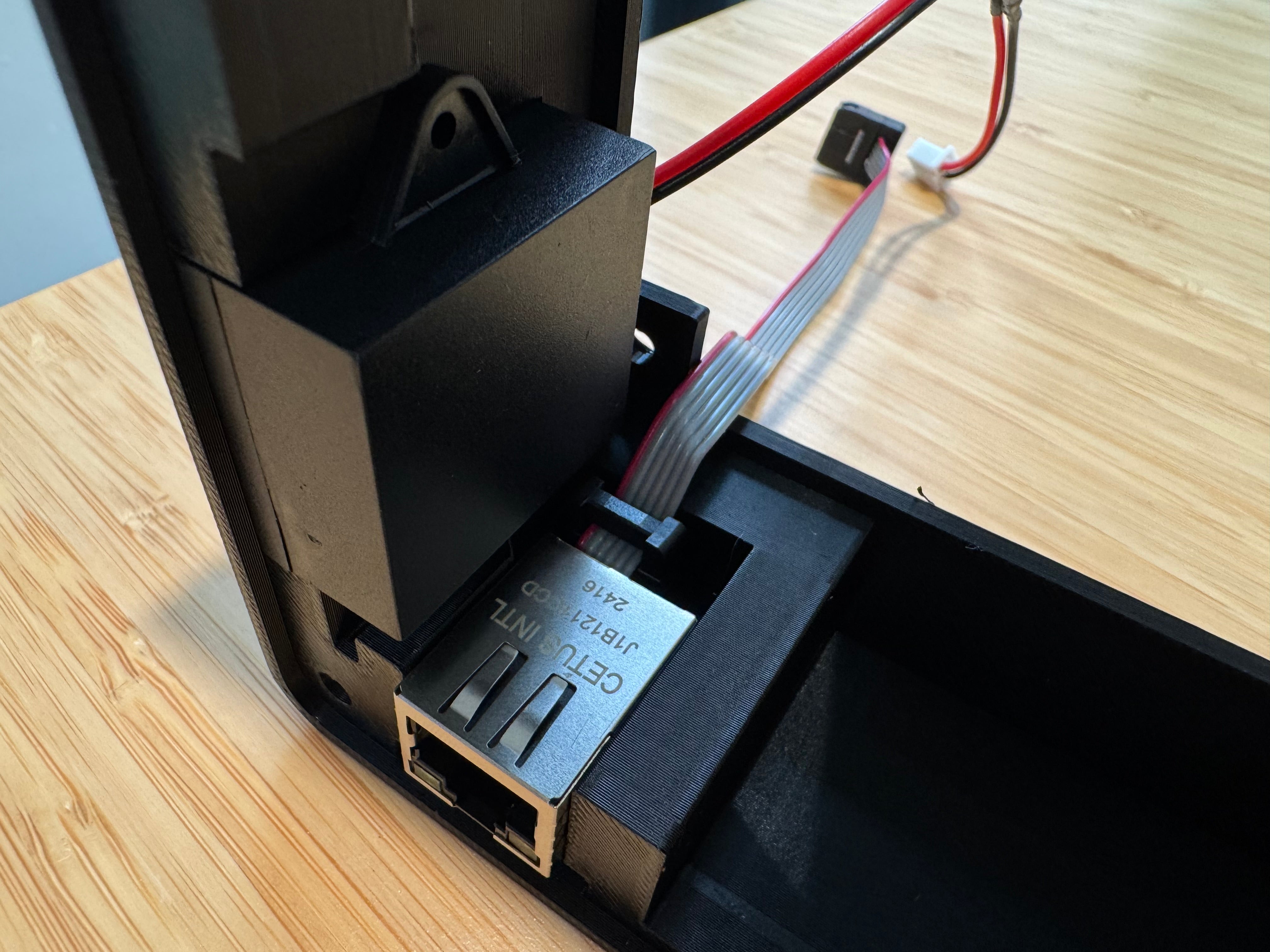
Ethernet port, USB port and speaker
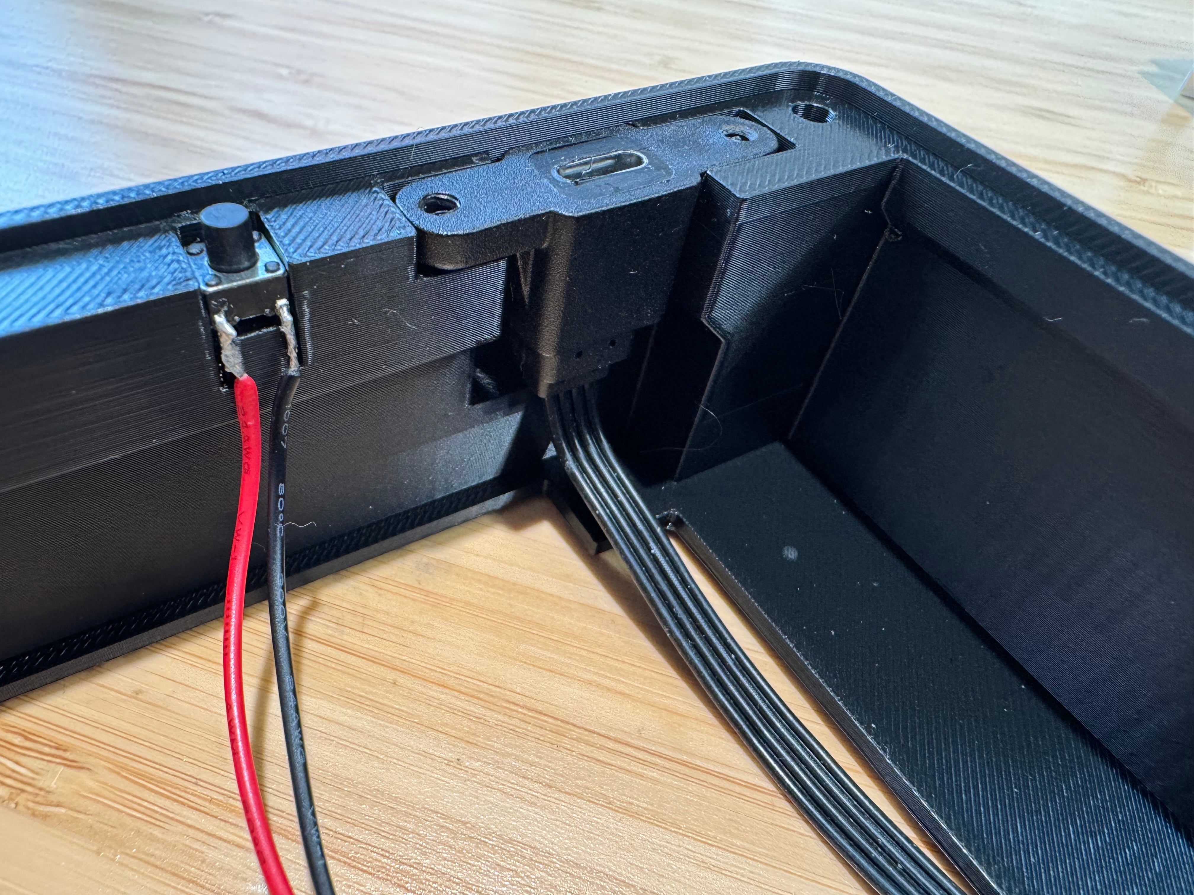
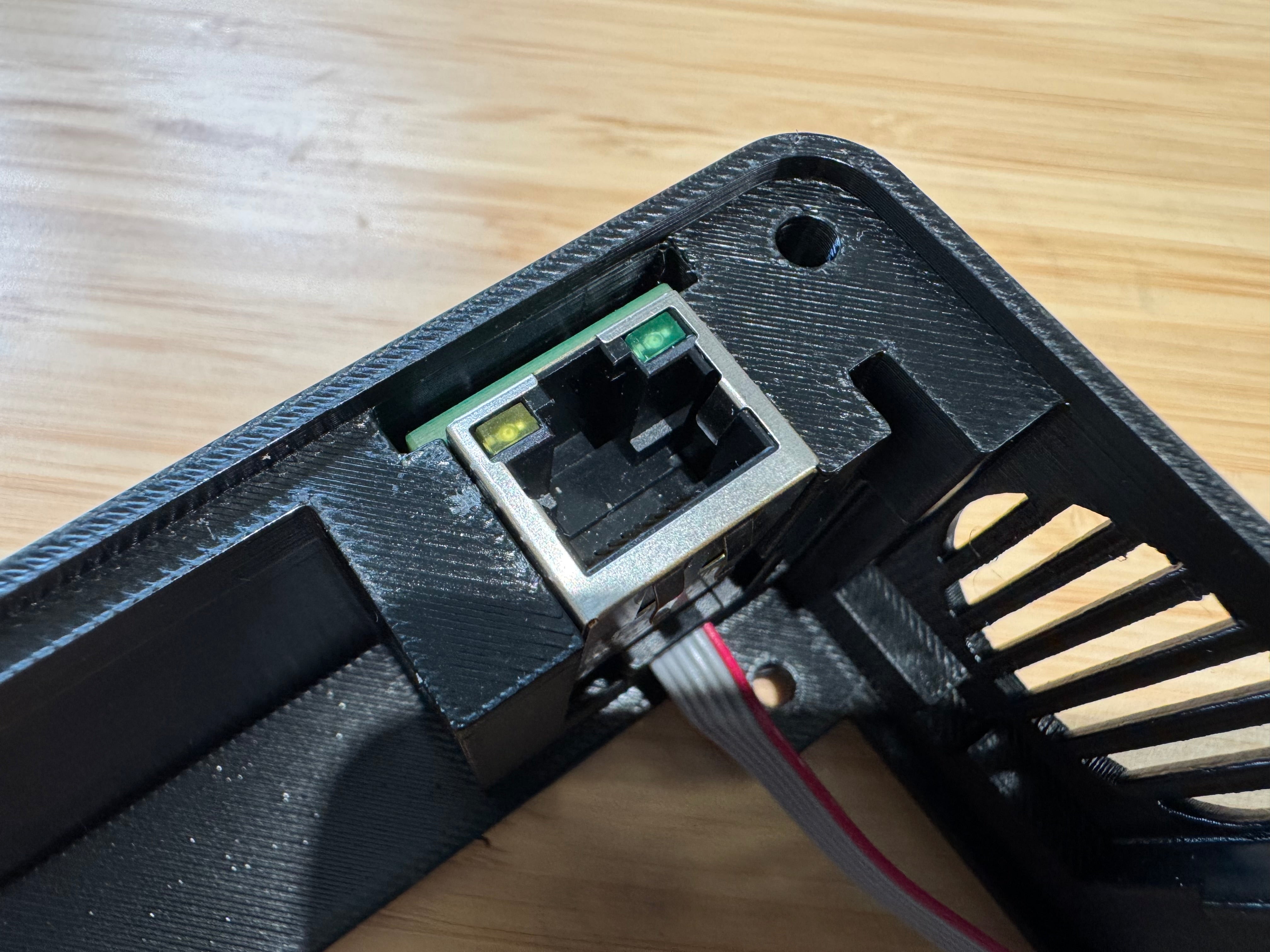
I would suggest fitting these next.
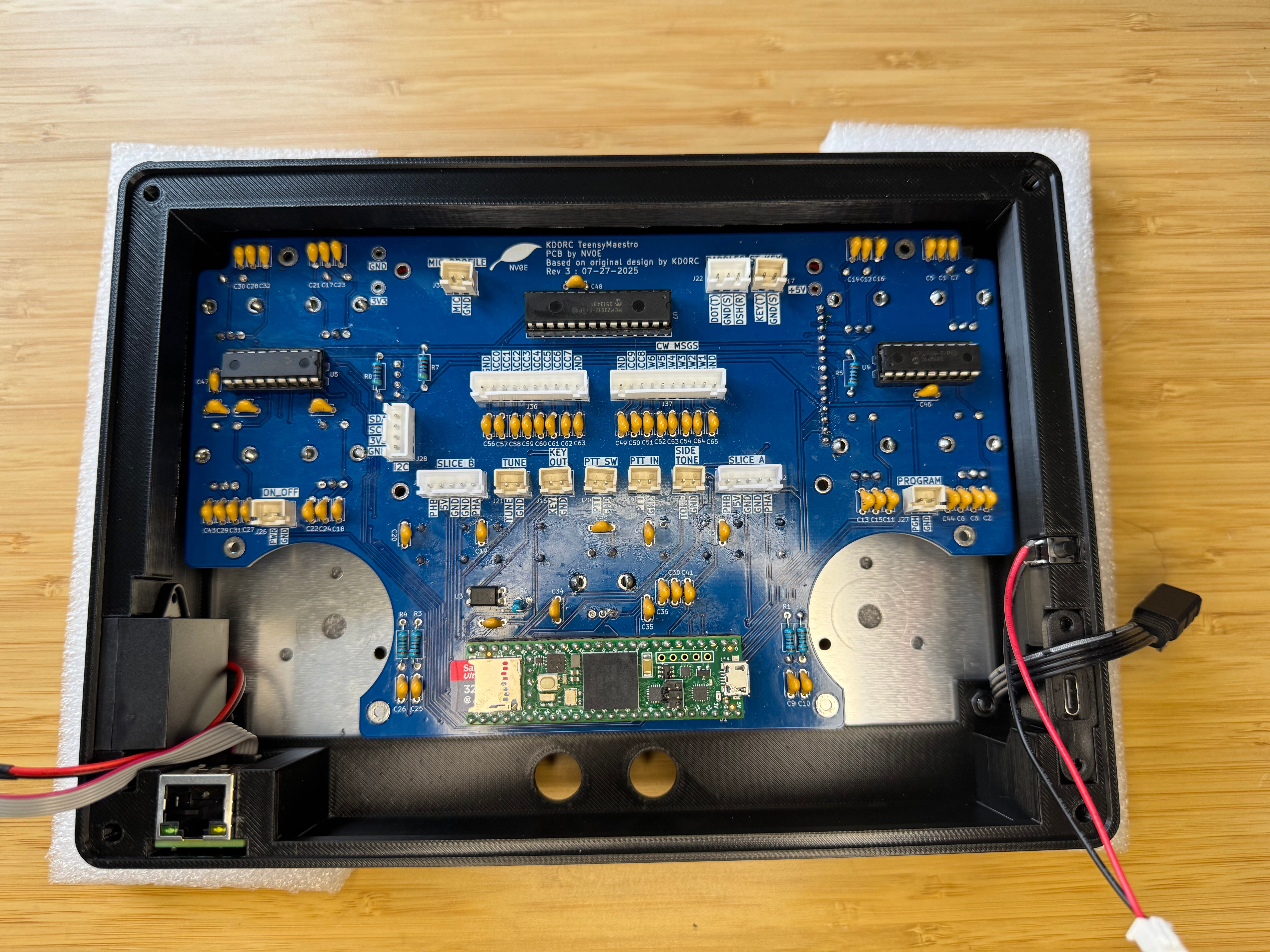
PCB
Lower the assembled PCB into the case (removing the nuts and washers if necessary).
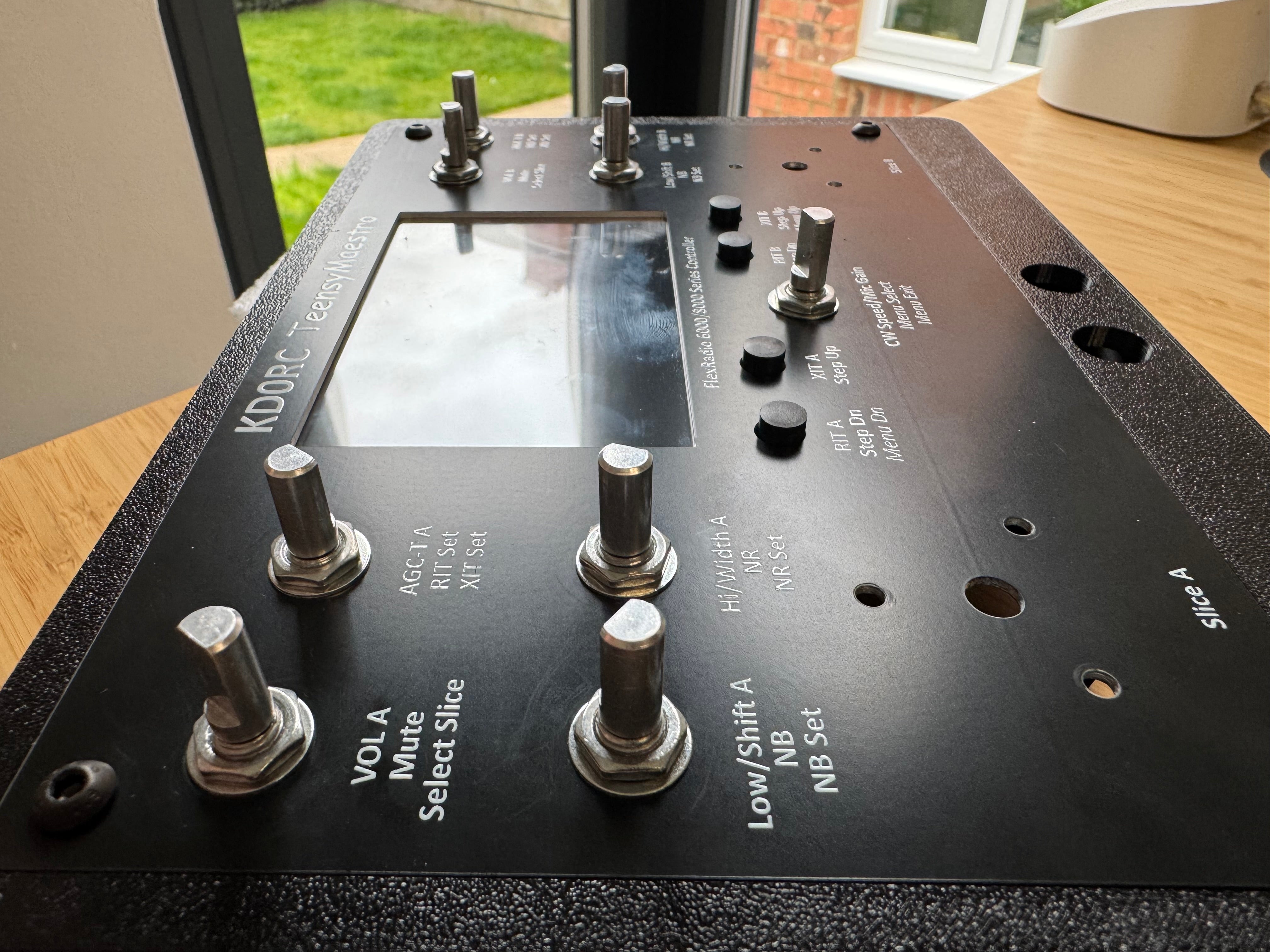
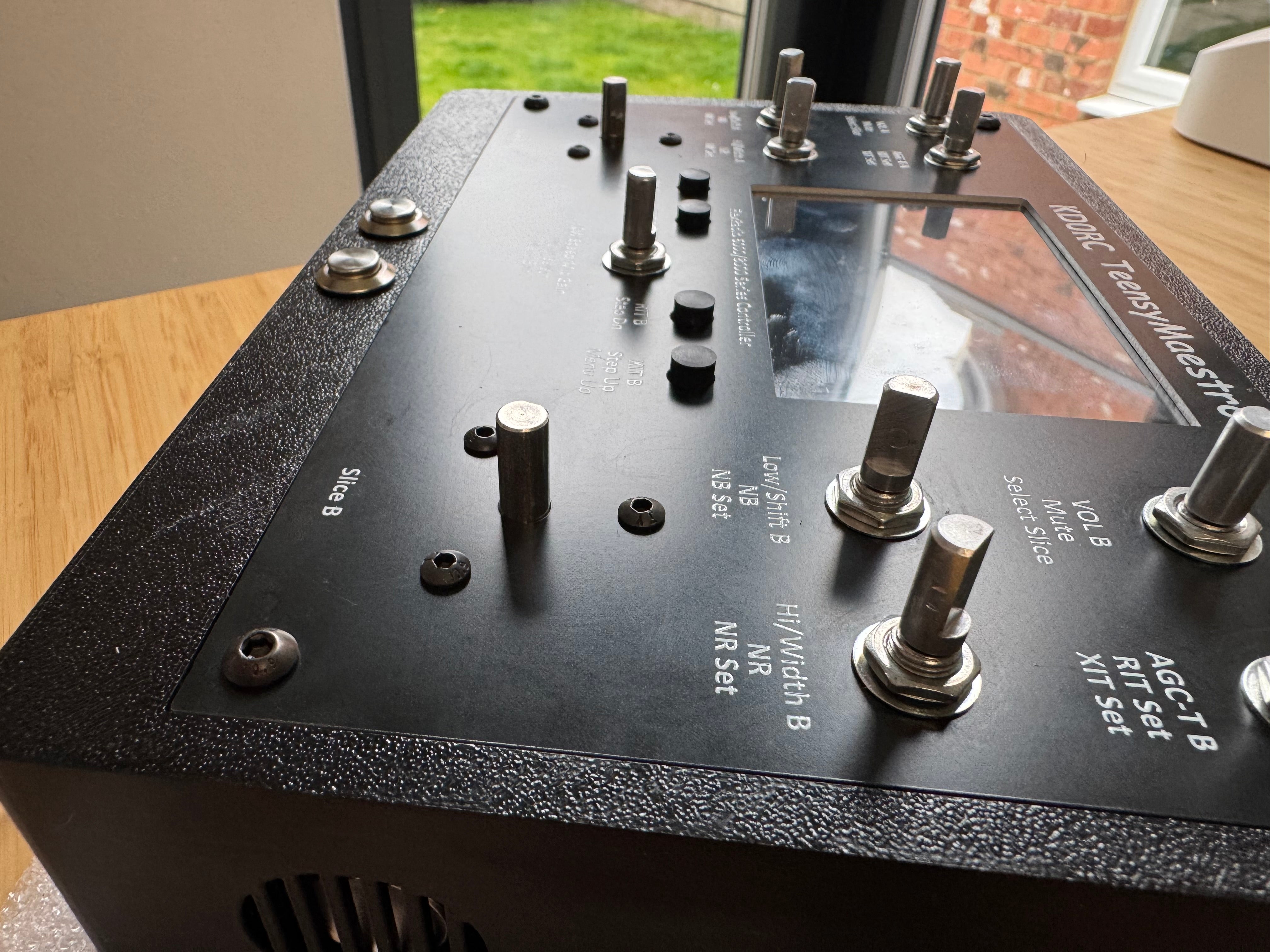
The nuts and bolts of the nine Bourns Rotary Encoders should be secured onto the front panel, holding it in place.
Update 6th October - via Len on the FlexRadio forums:
Placing an additional M7x0.75mm nut under the front panel on each encoder (except for the slice tuning ones). This is to help prevent any the panel warping and compression when we tighten the panel nuts on the top.
- Place the panel nuts on each control and screw them down far enough that with the panel in place, the nuts don’t touch it.
- Now place the panel on the controls so that it rests on the spacers and put washers and nuts on the controls. Only tighten them enough to hold the panel with no slack (just touching).
- Next, use a small screwdriver to turn the bottom nuts until they just touch the panel.
- Finally, tighten the top nuts hand-tight and you are done.
Front buttons
Fit the front buttons, securing with the nut.
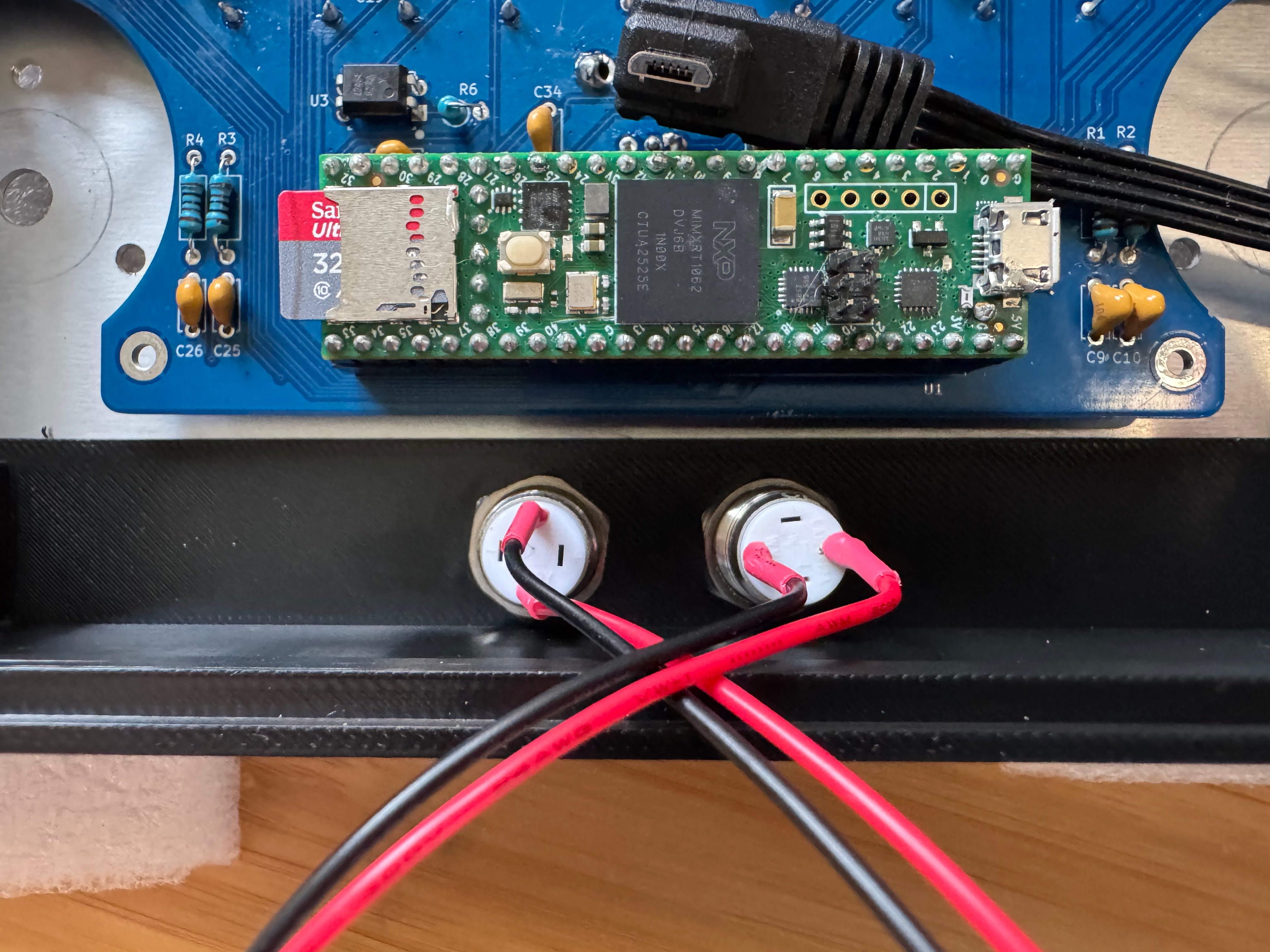
VFO encoders
Drop the large encoders into place, through the holes on the front panel.
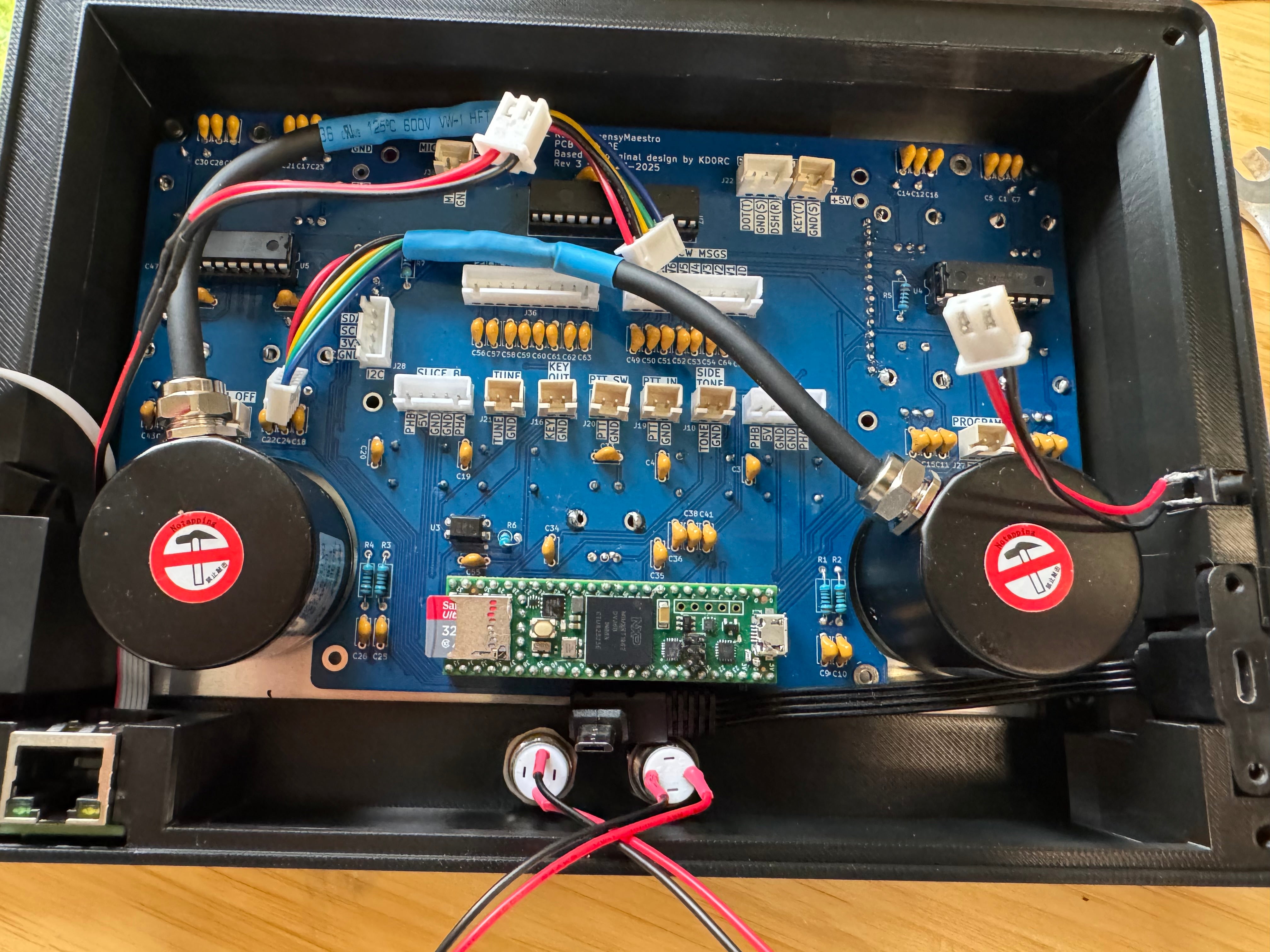
Secure them with the six M3x12mm nuts.
Connections
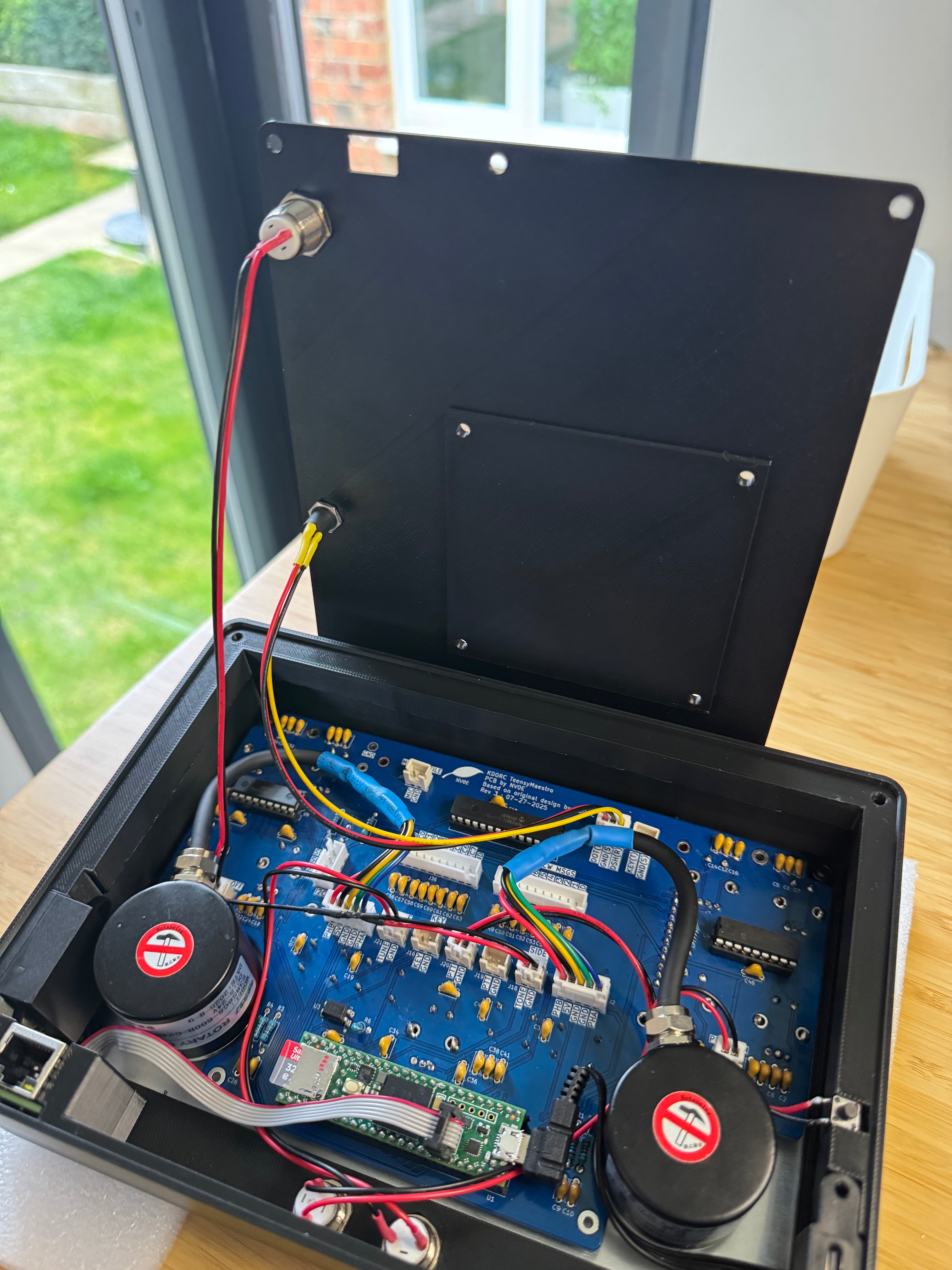
Connect all the leads, including the ones on the back panel.
Closing up the case
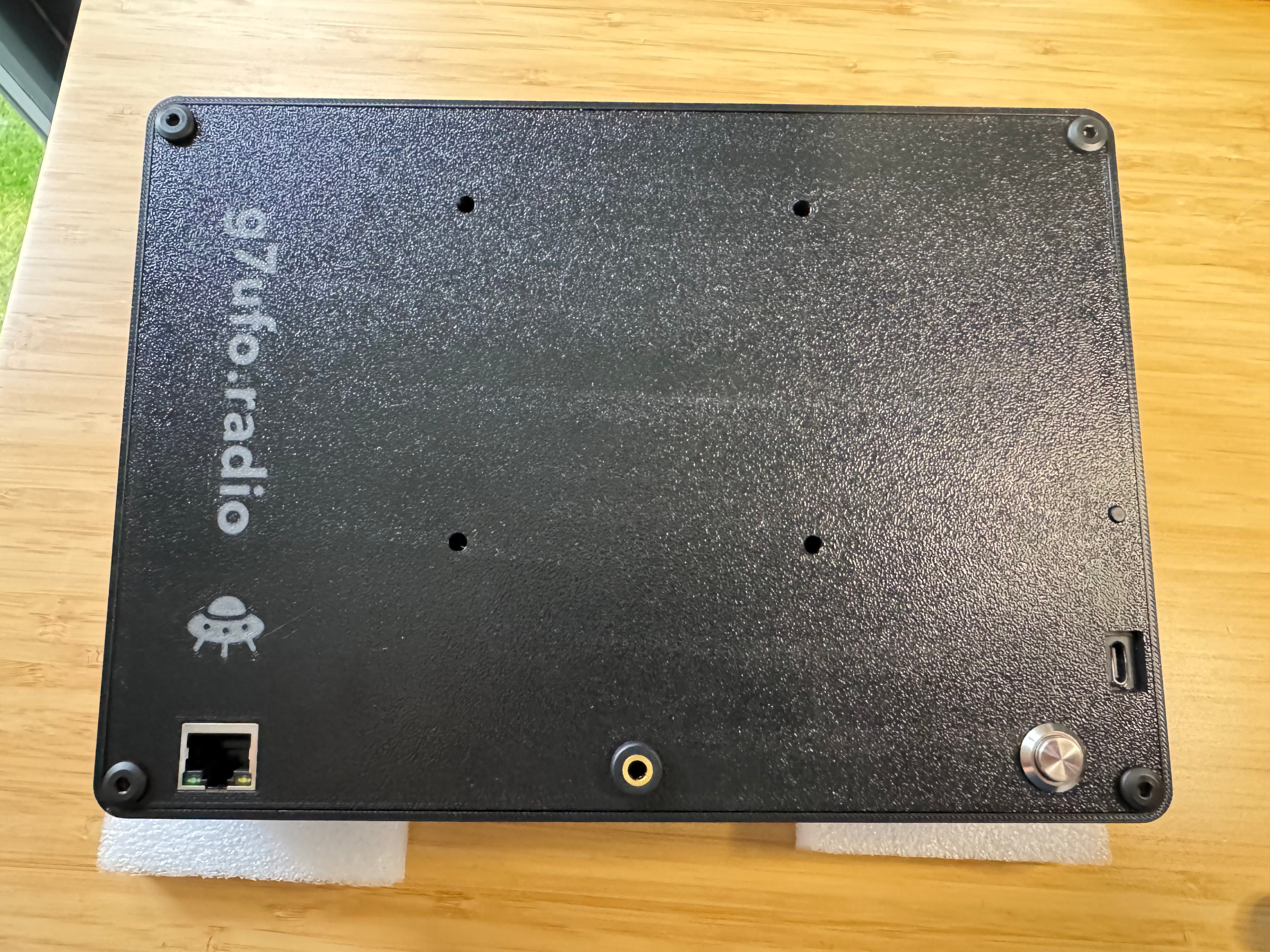
Fit the rear panel on the back, ensuring that the program button is sticking through the case.
Use the four M4x12mm nuts to secure the panel in place.
Front panel knobs
Fit the knobs.
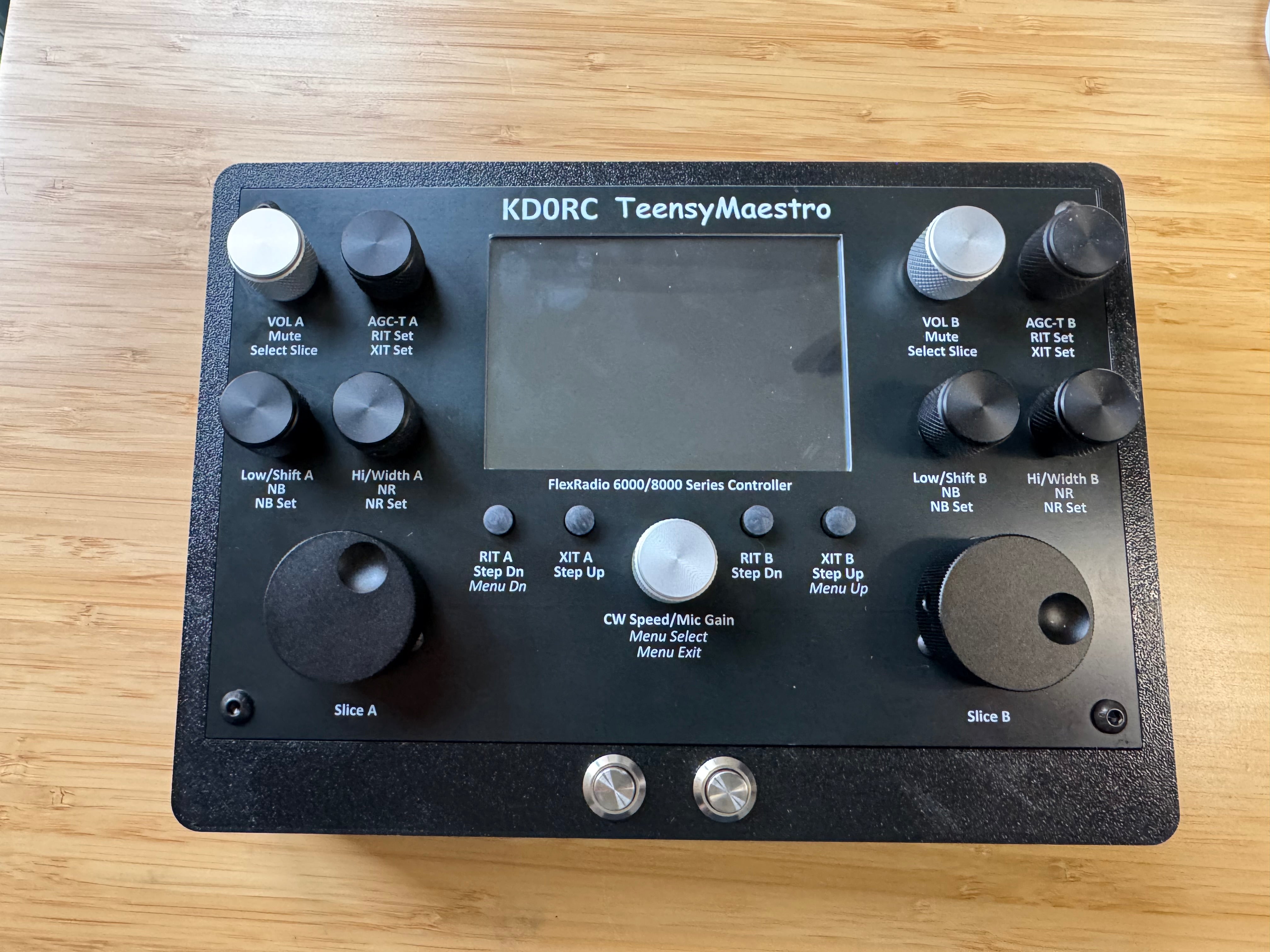
Firmware
This can be found in the releases section of Len’s GitHub page.
Please remember to update and add the MMConfig.ini file to the SD Card otherwise it will not boot.
QSO time
Time to give it a spin!