Build instructions for the K6ARK ultra light microphone kit
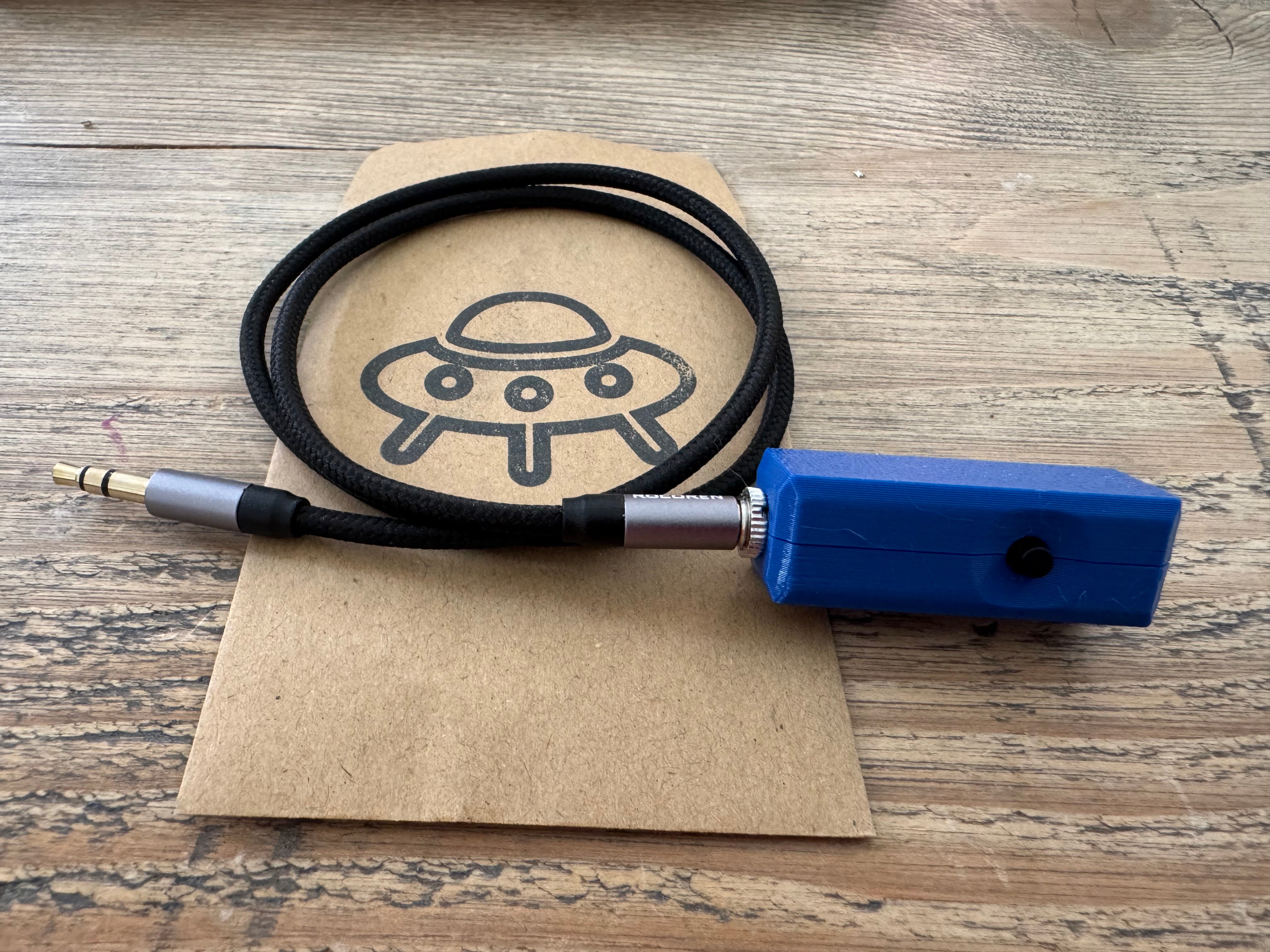
Important note
These instructions have been lifted from the printables.com page which contains the STL files and BOM you’d need to print your own case.
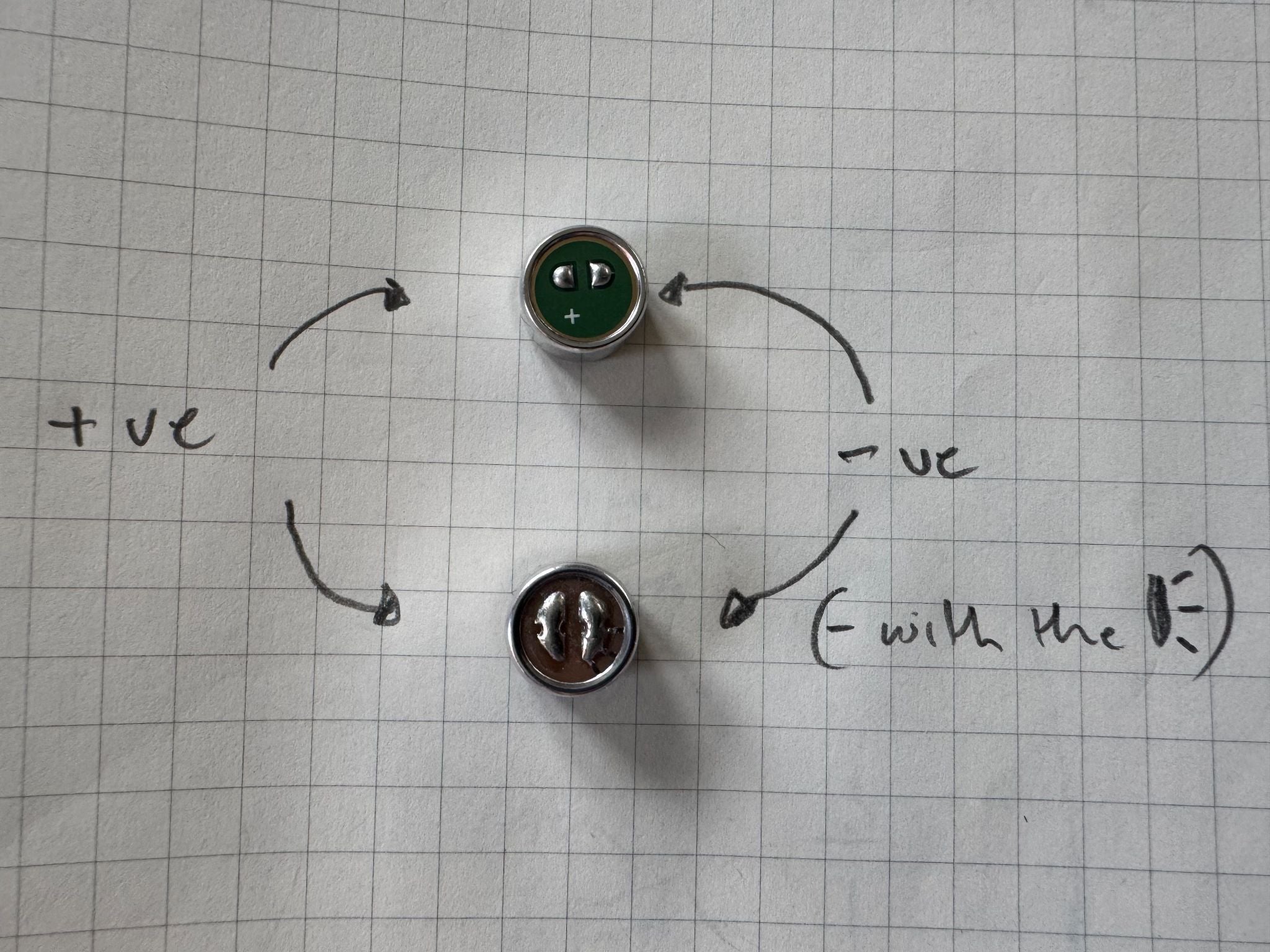
Microphone element polarity
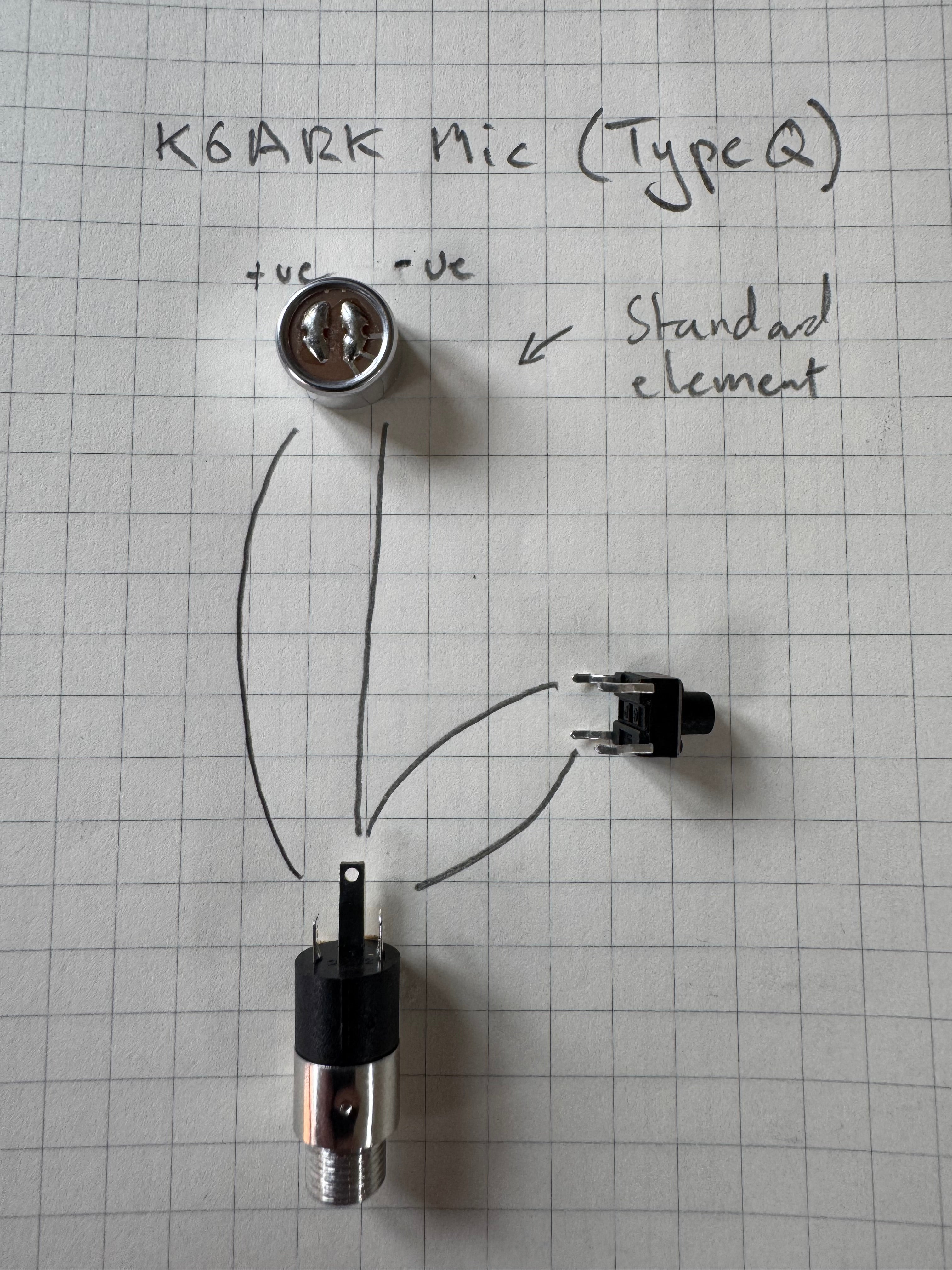
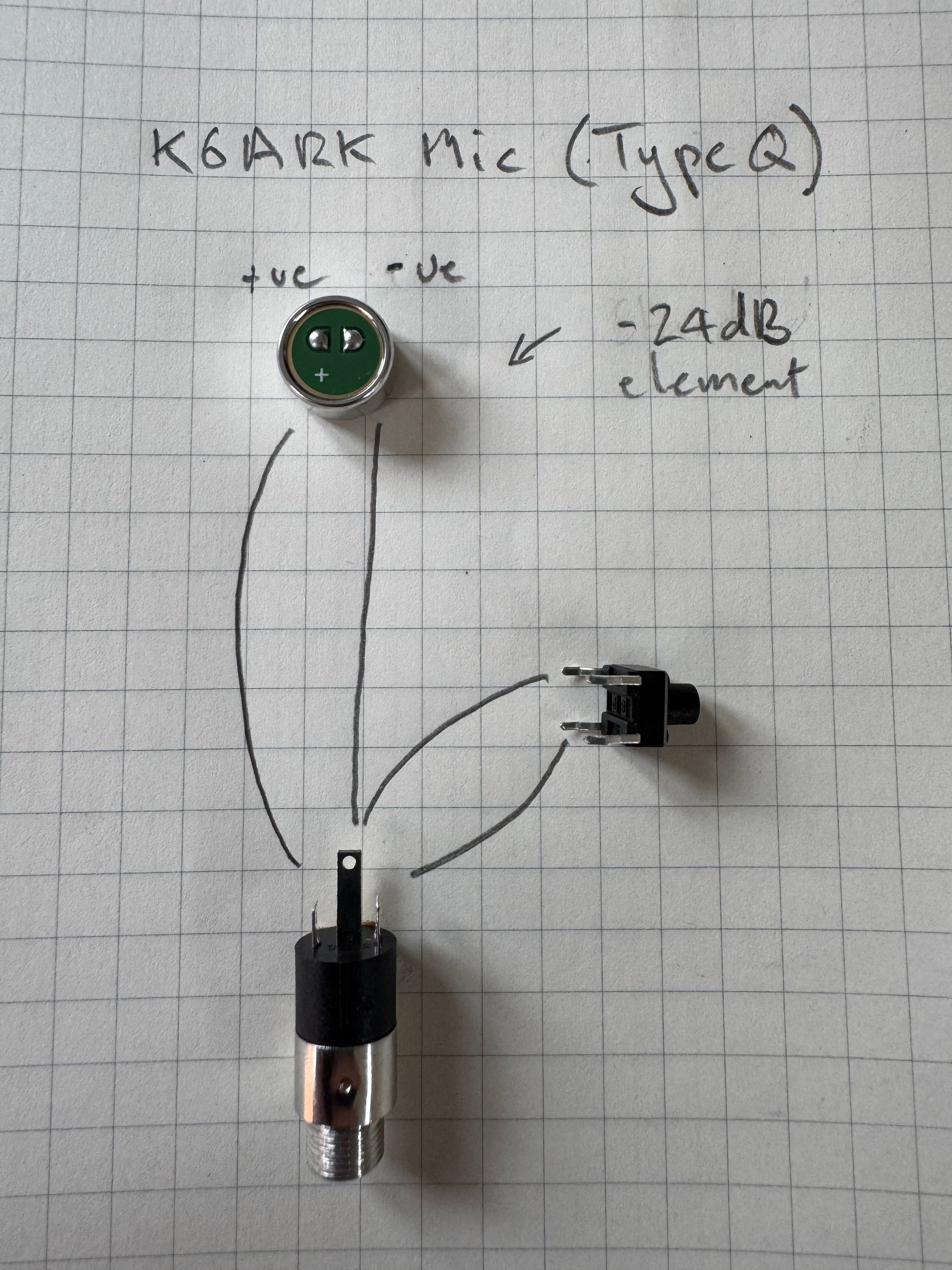
There are two elements available; the “Standard (CMA-6542TF-K)” (shown bottom) and “-24dB (AOM-5024L-HD-F-R)” (shown top).
Below is a picture which shows the polarity of the two microphones, as a guide.
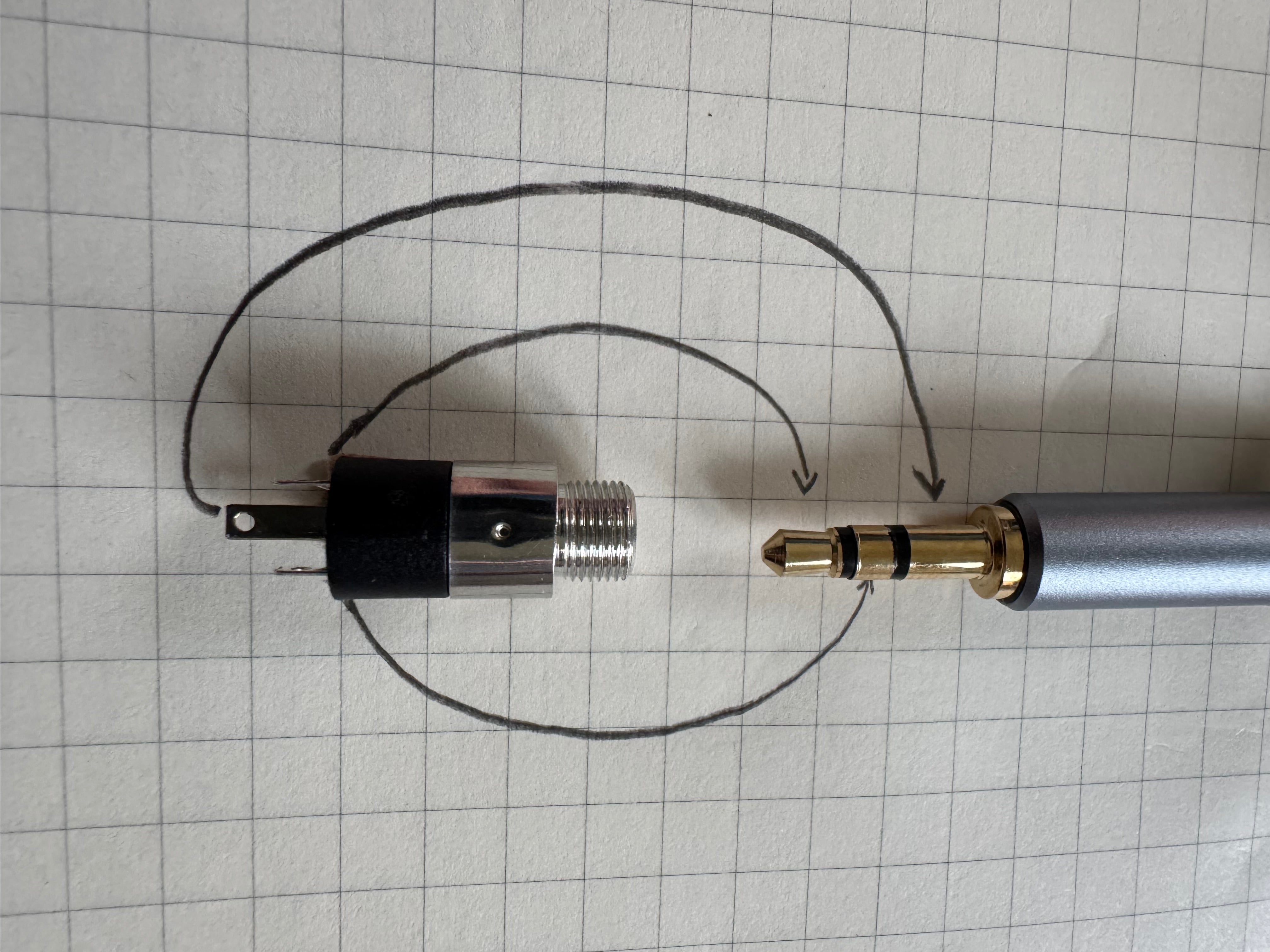
TRS socket connections
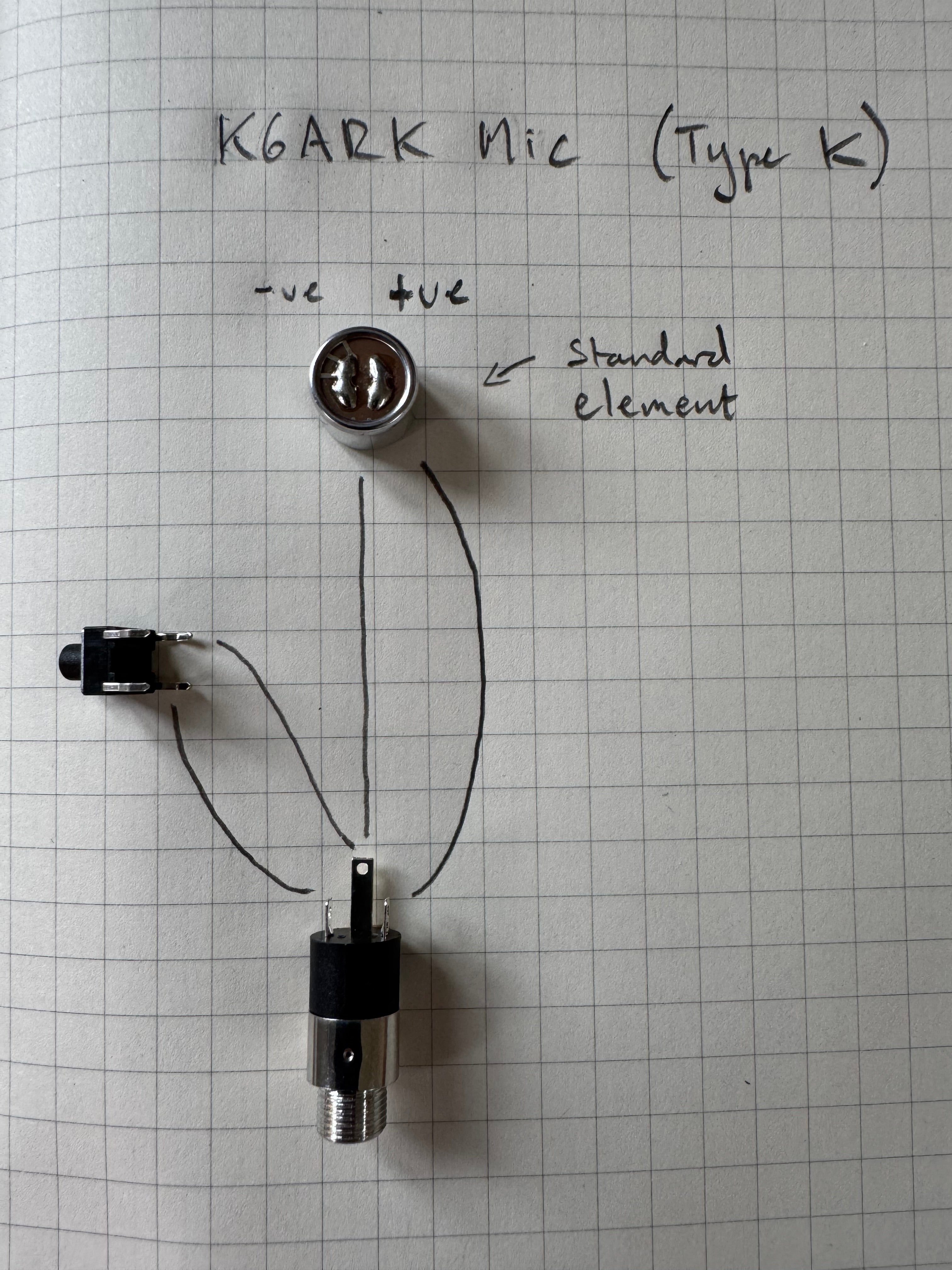
Cut wire and solder mic and switch to jack
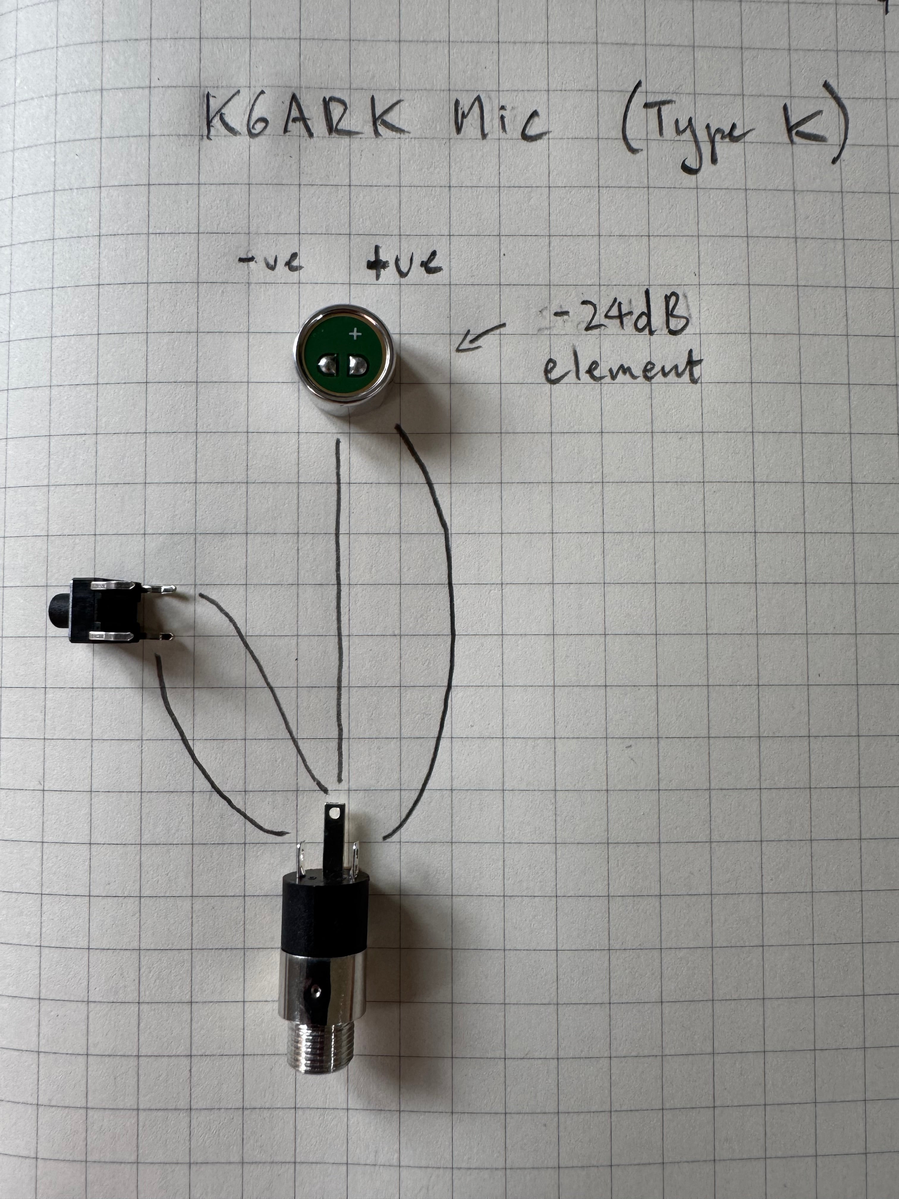
- Cut four pieces of wire to 30 mm in length and strip 3 mm of insulation from each end. Solder wires as shown in images below.
- Note “ground” traces on mic element. Connect that pad to the ground lug on the 3.5mm jack. Also note which switch lugs to use.
Type K
Supported radios:
- Elecraft KX2 & KX3
- BG2FX FX-4CR
- HF Signals sBitx & zBitx
Type Q
Supported radios:
- QRP Labs QMX & QMX+
- (tr)uSDX
- uSDX (not cloned 4-pin mic variants)
Test microphone
- Plug the mic into your rig and test. Check Elecraft manual for settings. You may need to change menu items for PTT bias.
- If mic does not work, try swapping the wires connected to the outer lugs of the jack and test again.
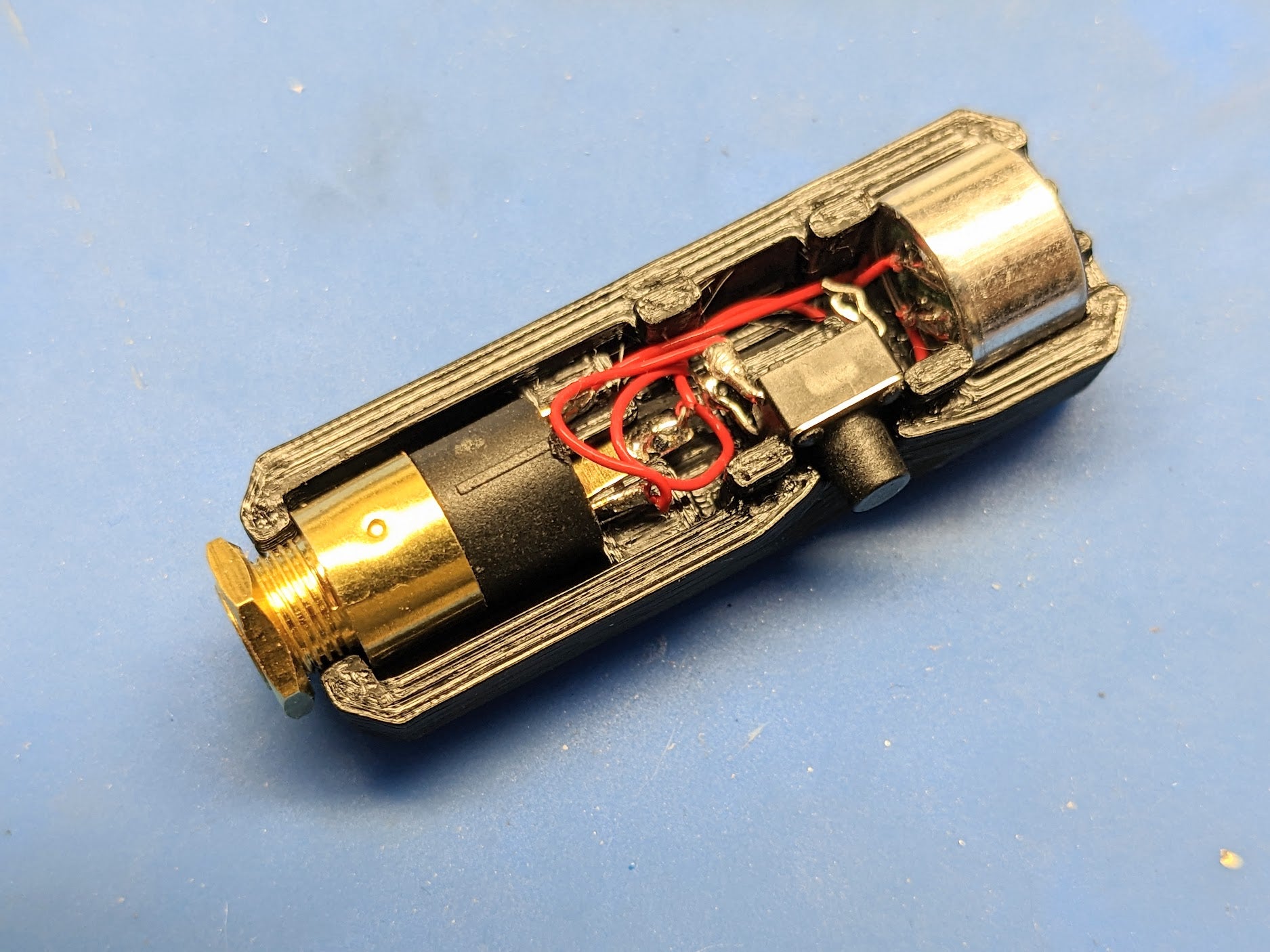
Install jack, switch, and mic into “Bottom” half of case
- Carefully press jack into place. Note ground lug position, centred in printed slot on base.
- Press switch into place, taking care not to damage lugs.
- Press mic element into place, taking care not to damage wind screen on front (not critical).
- Tuck wires into centre channel of bottom case ensuring wires will not be pinched in top cover.
Snap on top cover
- Ensure the wires are tucked in and will not be pinched, and snap on the top cover. Tighten the nut on the jack to finish the build.
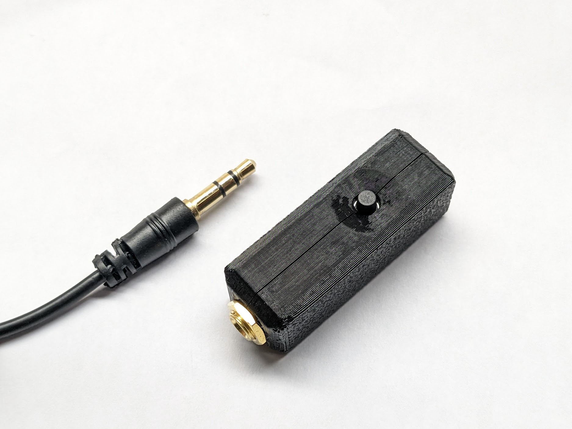
Now, get on the air and have some fun!
This work (text and physical case) is licensed under a Creative Commons (4.0 International License) Attribution-NonCommercial-ShareAlike.
Permission granted from Adam, K6ARK to reproduce this text and the kit in this store.